Common Bearing Failures
Did you know that more than half of electric motor failures start with bearing failure?
Determining bearing life is, at best, an educated guess primarily based on rotational speed, dynamic load, lubricant quality, and bearing size.
“L10” is the formula used by the bearing industry to predict bearing life.
This formula, based on RPM, load, hours, and bearing type (ball vs. roller), is a reliable tool for selecting the proper unit for an application; but bearing fatigue is also susceptible to real world issues such as contamination and excessive heat.
There are other factors that impact bearing life expectancy, such as motor manufacturers, who have been known to install undersized or inappropriate (for the application) bearings to save money.
In addition, maintenance personnel do not always lubricate routinely or correctly.
Now, back to the bearing fatigue – here are the five steps that outline the process:
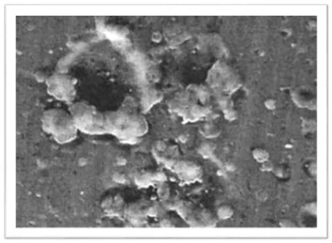
- Spalling: microscopic subsurface fractures of metal due to cyclic loading stresses create thin layers of surface separation, which flake off
- An increase of noise and vibration occur
- A change in critical dimensions occur
- More spalling is accompanied with increased noise, vibration, friction, and heat
- Advanced spalling leads to final bearing failure
While bearing fatigue is contingent on variables in the L10 formula, a majority of bearing failures can be attributed to a variety of other stresses in the following groups:
I. Thermal stress (Friction, Lubricant, Ambient)
As a general rule of thumb, and not considering use of certain synthetic or specialized lubricants, the rolling elements in bearings should not operate in temperatures above 100° C (212° F).
“80-90-100 Rule”: 80° is fine / 90° alarm / 100° shutdown
At the 100° C shutdown temperature and beyond, thermal expansion and lubricant breakdown will likely occur and cause failure.
Bearing temperatures are prone to surrounding air, wind, and rotor temperatures; the type, quantity, viscosity, and condition of lubricants; the bearing type itself (open, shielded, or sealed) and clearance; and the type of load (dynamic, direction, and cycling speed).
Click here to download ABB Baldor Whitepaper: "Oil Viscosity Selection"
Excessive heat can lead to lubricant deterioration and, ultimately, metal to metal contact.
Monitoring bearing temperature is essential, and can easily be done.
The most common tools for doing this include thermocouples and resistance temperature detectors (RTDs), which can be permanently mounted to locations on the bearing housing for continuous real-time monitoring.
TECH TIP: The color of the bearing components can indicate the temperature to which the bearings were exposed, ranging from shades of yellow to purple to blue.
Extreme temps (in excess of 205° C) can anneal the bearing race and balls, meaning that the materials will lose hardness.
Portable thermal imaging tools provide an inexpensive, quick, and efficient way to monitor bearing performance by using infrared (IR) thermography to visually identify variations in temperature.
II. Dynamic and static loading stress (Radial, Axial, Preload)
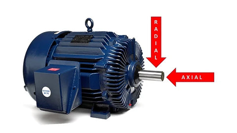
Load can be applied to bearings in one of two basic directions:
- Radial loads act at right angles to the shaft (bearing's axis of rotation).
- Axial (thrust) acts parallel to the axis of rotation.
Every rolling bearing requires a minimum radial load so that the rolling parts roll instead of skid.
For ball bearings, weight comes from the shaft.
In cylindrical roller bearings, radial load is derived from the belted application. If, however, a roller bearing motor is placed in a direct drive (coupled) application, rollers are likely to skid and generate heat.
Roller bearing motors should not be run more than 10-15 minutes without a radial load.
Use this formula to determine the minimal radial load:
Frm = (156 + 600n/nr) (dm/100)2
Where:
Frm = minimal radial load, N
n = operating speed, r/min
nr = speed rating for oil lubrication, r/min (from manufacturer's bearing table)
dm = mean diameter of bearing - 0.5(d+D), mm
Load comes in a variety of forms for horizontally and vertically mounted motors, including belted applications, misalignments, improper assembly, and incorrect bearings.
For example, vertical pump motor applications require medium or high thrust bearings to handle the thrust loads. Sometimes, people try to save money by mounting a horizontal motor in a vertical position, which may lead to premature failure not only for lubrication issues, but because the motor does not have a thrust bearing.
III. Vibration and Shock Stress (Rotor, Driven Equipment, System)
Bearing vibration damage can occur for a multitude of reasons including:
- Unbalanced equipment
- Rotor unbalance
- Loose mounting
- Machinery operations
- Environmental contributors like separate machinery, construction, and heavy traffic
Even bearings in stored or idle motors can suffer damage from shipping or vibration from surrounding conditions.
When bearings are not moving, there is no lubricant film between the rollers and the raceway. Add vibration to the picture, and the metal to metal contact will result in surface breakage called false brinelling, or washboarding.
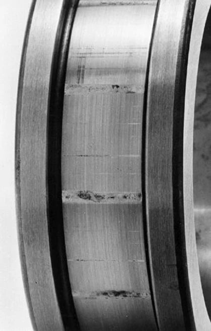
The stationary vibration damage pattern is specific to the type of bearing.
Look at this: Ball bearings create spherical patterns
Roller bearings produce fluting (lined pattern across inner and outer races)

IV. Environmental Stress (Condensation, Foreign material, Excessive ambient, Poor ventilation)
There are a multitude of factors in considering environmental stresses.
Choose the best lubricant for the job to avoid condensation issues. Lubricants are manufactured with various levels of moisture resistance, but they are not infallible, especially if not properly selected.
Condensation will leave a nasty rust on bearing surfaces and inside the motor; and this corrosion will lead to failure.
TECH TIP: Use desiccant bags to absorb moisture if equipment is in storage.
Foreign invaders can appear in all sorts of forms and damage the bearing or lubricant (and, subsequently, the bearing):
- Liquid
- Vapor
- Incompatible grease
- Abrasive particles
Ambient temperature relates not only to the surrounding air, but to conditions that arise from nearby threats.
For example: A leaking steam line that is steaming one side of the motor; or a motor in a confined space that is recirculating re-reheated air. Large difference between shaft and housing temperatures may lead to overheated bearings and lubrication.
V. Mechanical Stress (Loss of clearance, Misalignment, Shaft fit out of tolerance, Housing fit out of tolerance)
Various internal and external mechanical issues can lead to premature bearing failure.
- Several factors mentioned earlier, such as contamination or corrosion, may reduce shaft and housing clearances and create friction.
- Insufficient clearance may also be a result of having the wrong bearing on the equipment; check the part number or choose a properly sized bearing.
- Misalignment between the motor and driven equipment increase the dynamic load on bearing.
- An oversized or out of round shaft will cause a tighter fit bearing (is it hard to install or remove the bearing?). Machine the shaft to repair.
- An undersized or out of round housing will cause a tighter fit, as well (can you get the bearing in the housing?). Here, again, machine the housing to repair.
VI. Electrical Stress (Rotor dissymmetry, Electrostatic coupling, Static charges, Variable frequency drives)
Current discharges - oh, how we hate current discharges!
If you use VFD's, then this is old hat for you.
Shaft and bearing currents have also been referred to as shaft voltages, circulating voltages. or circulating currents. When shaft voltage - a.k.a. "common mode voltage" - leads to to ground through the bearings (bearing current), that's when we have a problem.
It is important to inspect bearings when they start making noise, before whatever is causing the problem leads to a catastrophic failure. At that point, it may not be as easy to discern the cause because the bearing will be destroyed.
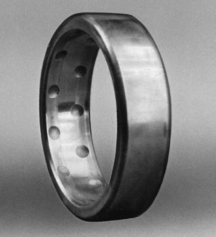
There are several signs if you are dealing with bearing current damage:
1. Discoloration - Balls and rollers will be dull or dark grey instead of shiny.
2. Pitting - Crater damage ranging in size from 0.1-0.5mm that can be seen with the naked eye.
3. Fluting - Lined pattern across the bearing races caused by resonance vibration over a period of time.
4. Micro-cratering - Most common damage, bearing race and rollers are dull and contains microscopic sized pits
Damaging shaft voltages that travel through the shaft to the bearing can arise from a number of issues.
The less common causes include voltage unbalance, unbalanced parallel circuits, and non-insulated through bolts.
The three most common causes, however, are magnetic dissymmetry, static electricity, and capacitive coupling.
1. Magnetic Dissymetry
Dissymmetry in core laminations is a predominant cause of magnetic dissymmetry, and is a result of differences in the magnetic circuit between the stator and rotor.
Motor laminations, whether segmented or composed of one piece, are not completely uniform. And the spaces between layered stacks vary, as well.
These small variances add up, and create unsymmetrical flux paths that run through the shaft, through the bearing, through the frame, and then return to the shaft via the other bearing.
2. Static Electricity
Electrostatic discharges are another leading cause of bearing current damage. Applications such as belt drives, fans, and blowers can produce damaging levels of static electricity from the driven equipment, especially in larger machinery.
3. Capacitive Coupling
In VFD applications, the rapid switching of insulated gate bipolar transistors (IGBTs) generates voltage in the motor rotor and shaft via the air gap between the stator and rotor.
This switching frequency is also called carrier frequency, and it is the rate at which direct current is "chopped" or broken up into synthetic AC blocks in the DC bus.
These induced voltages build up until they exceed the bearing lubricant's dielectric breakdown capacity. At this point, small discharges pulse through the bearing to ground.
Bearing damage occurs as this process continuously repeats. The same sort of process occurs in DC drives that utilize transistors and silicon controller rectifiers (SCRs) to convert AC into DC power.
Higher switching frequency means a higher rate of current and faster damage. However, lower frequencies on VFDs will be audibly louder, so it is a double-edge sword: you either deal with more noise and less damage, or less noise and more destruction.
Each of these bearing failures can be avoided with proper equipment configuration and maintenance. Square One Electric has a team of skilled technicians that can help diagnose your bearing issues and help to find solutions.
Content credit: Electrical Apparatus Service Association